|
|||||||||||||||||||||||||||||||||
|
Rules: Robo-Magellan is a robotics competition emphasizing autonomous navigation and obstacle avoidance over varied, outdoor terrain. Robots have three opportunities to navigate from a starting point to an ending point and are scored on time required to complete the course with opportunities to lower the score based on contacting intermediate points. The robot must not be constructed in such a way as to damage the environment or other robots. See "Safety" for other restrictions. No robot may weigh more than 50 pounds nor may it use an internal or external combustion engine. The robot must fit inside a 4' x 4' x 4' cube for the entire duration of its run. Robots must be autonomous. Remote control is not allowed, with the exception of the remote control safety switch. The course will be outdoors with both natural and man made terrain and obstacles. The terrain may include pavement, dirt, small rocks, grass, hills, gullies, trees, curbs and weeds. This list is not comprehensive. The robot will not need to traverse a water obstacle to complete the course although weather conditions may make some surfaces wet and/or soggy. The contest will not necessarily be postponed in the event of inclement weather. Robots will be placed at a designated starting point prior to each run. The destination and bonus way-points will be designated with latitude/longitude coordinates and marked by 18", orange, plastic traffic cones. Way-points will be specified as degrees and minutes with minutes carried out to four positions right of the decimal point (N 47 22.1245 W 122 32.0493). The datum is WGS84. The total straight-line distance between the start and destination will be less than 1,000 feet. However, the shortest route may be longer due to obstacles. The route taken from start to destination, including bonus way-points, may be significantly longer than 1,000 feet. Physical Platform: The EVErobotics Robo-Magellan entrant is built on a Traaxxas Stampede 1/10th scale electric truck frame. We were able to reuse the stock speed controller and steering servo by substituting the radio receiver module's control signals with pulse-out signals output by the Javelin micro-controller. The control signals consist of 50 Hertz positive TTL pulses of between 1mS and 2mS with 1.5mS as null for both steering and throttle.
Controllers: The micro-controllers used in the robot are a Javelin Stamp made by Parallax, and an ARMmite single board programmable controller made by Coridium. We presently use the Javelin to manage the sonar sensors and control throttle, brake, and steering. The Javelin speaks Java (or a subset of Java with hardware control libraries), and the ARMmite is programmed in C or BASIC (C for me thanks). We use the ARMmite to process data from the GPS module and the electronic compass. The ARMmite stores an array of GPS way-points which it uses to calculate the robots heading, desired heading, and cross-track error, then it relays suggested steering information to the Javelin serially. The ARMmite was an exciting find; it speaks ANSI/ISO C99 and the compiler is GNU C. The development software is free, easy to use, and allows you to use the editor of your choice (Notepad++ is the way to go). The ARMmite development software is also distributed with hardware control libraries (all open source). For language purists the ARMmite and the Javelin are ideal, the hardware libraries are open source and the code is perfectly familiar if you know Java or C/C++. Furthermore, the ARMmite's specs blow its competition out of the water; it's ARM7 processor runs at 60Mhz (the Javelin runs at 25Mhz, and the fastest Parallax has to offer, the BS2sx-IC runs at 50Mhz), the ARMmite executes 10 million+ instructions per second (Parallax's best the BS2px-IC only runs 19 thousand, and the Javelin runs a pitiful 8,500), the ARMmite can be programmed over USB, Bluetooth, Zigbee (wireless), or serial RS-232; the list of advantages goes on. The ARMmite is a powerful and capable industrial grade controller sold at the same price as the hobbyist grade Parallax products. Alright, enough with the sales pitch, I don't work for Coridium, I promise. Lastly we have integrated a fully fledged embedded computer into our design. The AR-B5230 mother board made by Acrosser processes data from cameras and other sensors to form a map of the robot's environment and make complex decisions based on all the information available to it. The computer also serves as an embedded development platform for its own software as well as the attached peripheral controllers, and as a means for remote control and/or remote monitoring of the robot via an 802.11g wireless network interface.
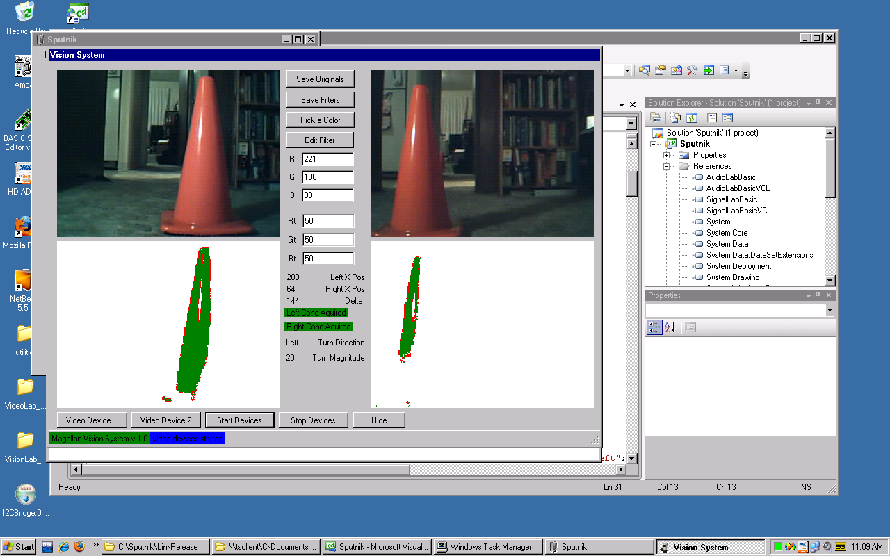
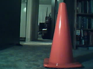
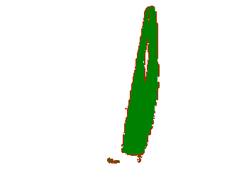
Sensors: The sensors that have been acquired and installed so far are a GPS module made by Parallax, an electronic compass, three sonar range finders also made by Parallax, two Sharp GP2Y0A02YK0F IR rangefinders, a rotary encoder, and two USB cameras. The GPS module provides data for navigation between way-points, the compass gives the robot accurate heading information, and the sonar modules provide data for obstacle avoidance, the cameras are used in a machine vision system which identifies 18" orange traffic cones and in the future will do more advanced analysis of the robots environment, and a rotary encoder mounted on the motor acquires motor rpm. Other useful sensors include switches affixed to feelers to ensure that the robot can detect and navigate around obstacles invisible to its other sensors, as well as an accelerometer to measure incline etc. to be used in an inertial navigation system.
Pictures of Sputnik: Click on image for high resolution version.
Watch Movies of Sputnik in Action: Clip1, Clip2, Clip3, Clip4 Theory of Operation: Our robot uses a GPS module, an electronic compass module, and a rotary encoder to navigate between an array of way-points. Each way-point is a longitude latitude coordinate pair that has been manipulated by an expression which converts the coordinates to base ten values using dimensional analysis. Once the coordinates are converted to base ten coordinate pairs it does math with them. The robot converts the rectangular coordinates to polar form an then it finds theta, the angle between north and target way-points, this becomes the robot's desired heading. Then it figures out which direction it should turn based on the values of its desired heading and its present heading (given by the electronic compass). Lastly it computes cross-track error (the difference between the desired heading and the present heading). Using this information the robot can decide where it needs to go and how to get there. The sonar sensors provide a means for obstacle detection and avoidance, but play no part in macro-navigation, if there were no obstacles they would not be used at all. Lastly, two USB web-cameras and an embedded PC running WindowsXP and a custom application written in C# enable the robot to identify 18" orange traffic cones that mark the way-points and touch them (GPS is only accurate enough to put the robot in the neighborhood of the way-point). The cameras will also be used for an adaptive vision system to aid in obstacle detection and avoidance. Bill of Materials: Formats: Links:
|


